Thermoacoustic machines
Thermoacoustic machines
Thermoacoustics deals with reversible energy conversion and interaction between heat oscillations and sound waves in gases and involves research in acoustic, thermodynamic, fluid dynamical phenomena and system dynamics. Thermoacoustic machines convert fluctuating low grade thermal energy into sound waves of high amplitude which in turn can drive thermoacoustic refrigerators and heat pumps or can be directly converted into electrical energy using an electrodynamic or piezoelectric transduction mechanism. Such machines have a high potential for the development of sustainable and alternative energy systems by utilizing low temperature waste heat recovery, biomass and gas combustion heat and solar energy, respectively. Promising features of thermoacoustic machines are high reliability, lack of moving parts (with the exception of the acoustic resonator), quietness, low cost and generally environmental friendliness.
Overview
In thermodynamics the states density, temperature and pressure are coupled in a gas: qualitatively, it can be said that pressure oscillations go along with corresponding temperature oscillations, if a constant system volume is assumed. In thermoacoustics, the interaction of pressure waves (sound) and heat in a working fluid can be used for energy conversion. A thermoacoustic refrigerator (TAR) uses mechanical power in the form of sound waves to pump heat across a specially designed thermoacoustic stack. A thermoacoustic engine (TAE) works the other way round: a temperature gradient across a stack can produce sound-waves and thus transform heat into acoustic power.
Although basic thermoacoustic effects have been known for a long time (first phenomenological descriptions in literature date back to the early 19th century) [1], a rigorous and complete mathematical description had not been presented until ETH-Professor Nikolaus Rott published his linear thermoacoustic theory, which was completed about 1980. [2]. In the following years, increasing efforts were made to explore the theory, designs and applications of thermoacoustic machines [3] [4] [5]. It had been realized that - particularly for refrigeration - this unconventional technology features multiple advantages in comparison to standard vapor-compression refrigerators: no dynamic sealing and lubrication is required and there is no need for (usually harmful) refrigerants in the thermodynamic cycle [6], which makes thermoacoustic devices environmentally friendly and attractive for high-reliability applications. Furthermore, it is possible to steer and hold the temperature at a desired setpoint using basic feedback control techniques, while conventional cooling technologies often rely on binary control schemes and oscillate about the setpoint.
These advantages predestine thermoacoustic cooling, for instance, for high -accuracy applications in cryogenics. In comparison to conventional cryo-cooling technology, thermoacoustic coolers are relatively cheap, reliable and require low maintanance. However, where every-day cooling applications are concerned, thermoacoustic technology is currently not capable of competing with well-engineered vapor compression refrigerators. Considerable drawbacks of state of the art TARs are their low power density (conventional refrigerators reach high power densities by exploiting the enthalpy of the refrigerant's phase change) and their comparably low efficiency.
Nevertheless, it is not unlikely that these drawbacks can be resolved through specific research efforts and in fact, there is a growing interest in the research community to make these devices more competitive. Thermoacoustic energy conversion has not received much attention in feedback control research in the past decades. On this website, we present some projects which are supposed to initiate automatic control research in thermoacoustic refrigeration at ETH's Automatic Control Laboratory.
Thermoacoustic operation principles
Thermoacoustic refrigerators can be subdivided into travelling-wave-systems and standing-wave systems. In this project, only the latter are considered so far. Furthermore, considerations are restricted to devices which are powered by electrodynamic drivers, for example common high-fidelity loudspeakers. For understanding such a TAR, two fundamental mechanisms are relevant: standing acoustic waves in a tube and the Brayton cycle. In the following, qualitative explanations of both are given.
Standing acoustic waves in an open/closed tube
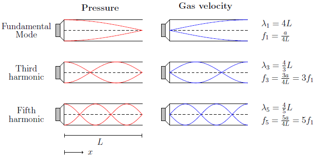
Consider a simple, straight tube of length L with an open end and a loudspeaker being attached to the other end. Assume that the driver generates a sinusoidal pressure wave of frequency f as input signal. Depending on f, standing acoustic waves of different orders will be observed, due to the interference of the incident and the reflective wave. In a standing wave, pressure and the gas parcel's velocity are 90 degrees out of phase. The figure above qualitatively shows gas pressure and flow amplitudes for the first three resonance-modes.
The boundary conditions are the following: the open end is a pressure node and a velocity anti-node. The closed end is a a pressure anti-node and a velocity node. Thus, for an open-closed configuration, the higher-order resonance frequencies are uneven multiples of the fundamental resonance frequency.
The Brayton cycle and the thermoacoustic stack:
Next, assume that a small gas parcel oscillates back and forth in a thin pore of a solid, subject to the dynamics of the previously described fundamental standing wave. Assume that the pore is placed approximately in the middle of the tube. Assuming that the gas is in good thermal contact with the solid, the interaction of the standing wave, the gas in the pore and the solid can be interpreted as an idealized thermodynamic cycle process: the counter-clockwise Brayton cycle. Its four steps are sketched and described qualitatively in the following.
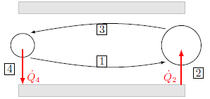
[1]: Assume that a small gas parcel is displaced from its original location on the speaker-side of the pore to the right. The gas pressure decreases, which may be idealized as adiabatic expansion. Consequently, the gas parcel cools down. At the end of step one, it is assumed to be colder than the surrounding solid.
[2]: Isobaric heat transfer: the temperature difference between gas and solid causes heat transfer from the solid to the gas parcel.
[3]: The acoustic wave draws the gas parcel back to its original location on the left. Adiabatic compression takes place, the gas parcel is now warmer than the surrounding solid.
[4]: Isobaric heat transfer: in the last step, heat is transferred from the gas to the solid. The process restarts at step 1.
In this way, mechanical work in the form of acoustic waves is transformed into a heat flow: heat is pumped against a temperature gradient. If the solid's thermal conductivity is low enough to prevent rapid balancing of this "thermal disequilibrium" through heat conduction, a steady temperature gradient can be established.
This is the (very simplified) working principle of the thermoacoustic stack, and at the same time, it explains its name. By `stacking' many pores in parallel, large heat flows can be produced. Note that even for a strong standing wave in air at ambient pressure, the gas displacement will typically be of a magnitude of a few millimeters only. By using a sufficiently long stack, large temperature differences can be reached (bucket-brigade principle). Since the stack can be considered as storage for `packages' of heat which are transported against the natural temperature gradient, two stack material requirements are obvious: first, a sufficiently large heat capacity is desirable. Second, the stack material should have lower thermal conductivity than the working gas. However, it is important to mention that a too low thermal conductivity would be harmful for the process because it also affects the heat transfer between solid and gas. A trade-off between low heat conduction in the stack and good heat transfer coefficient between solid and working fluid is required.
Demonstrator: Thermoacoustic refrigerator, standing wave system
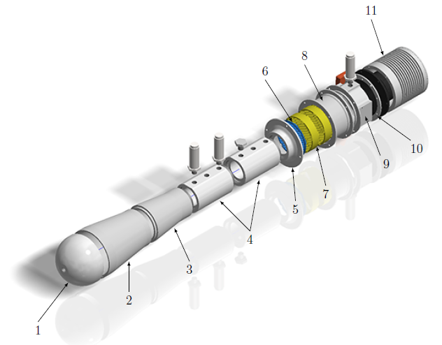
The modeling, design and construction of our a loudspeaker-driven TAR has been completed.
The figure shows an exploded assembly drawing of the final design and labels the main components (1: Compliance half-sphere; 2 and 3: Diverging Cone segments; 4: Cold Duct segments; 5: Reducer Cone; 6: Cold HX; 7: Stack segments; 8: Stack Holder; 9: Warm Duct; 10: Adapter Plate; 11: Speaker Housing.).
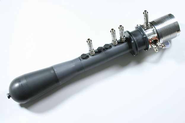
The laboratory-scale experiment uses air at ambient pressure as working fluid and is designed for 2 Watts of cooling power at a temperature difference of 25 K.
Literature:
- [1] B. Higgins, "On the sound produced by a current of hydrogen passing through a tube", Journal of Natural Philosphy, Chemistry und the Arts, Vol. 1, pp. 129-131, 1802.
- [2] N. Rott, "Thermoacoustics", Advanced Applied Mechanics, Vol. 20, pp. 135-175, 1980.
- [3] J. Wheatley, T. Hofler, G. Swift, and A. Migliori, "Understanding some simple phenomena in thermoacoustics with applications to acoustical heat engines", Am. J. Phys, Vol. 53, No. 2, pp. 147-162, 1985.
- [4] G. W. Swift, "Thermoacoustic Engines", The Journal of the Acoustical Society of America, vol. 84, p. 1145, 1988.
- [5] G. Swift and S. L. Garrett, "Thermoacoustics: A unifying perspective for some engines and refrigerators". Acoustical Society of America, 2003.
- [6] A. Waele, "Basic operation of cryocoolers and related thermal machines", Journal of Low Temperature Physics, vol. 164, no. 5-6, pp. 179{236, 2011.