Autonomous RC car racing
The ORCA (Optimal RC Racing) Project developed (and improves) a test bed consisting of a race track, a infrared camera based tracking system and modified 1:43 dnano RC cars, in order to study control algorithms allowing high-speed, real-time control. On the test bed different fast MPC algorithms are implemented, allowing the cars to online plan their trajectory only based on the track layout and avoid other cars. To allow competitive racing between automatically controlled cars, game theoretical methods are used to derive new control strategies, suited for competitive racing.
Hardware
The hardware of the ORCA project is consisting of a control loop fully built by students.
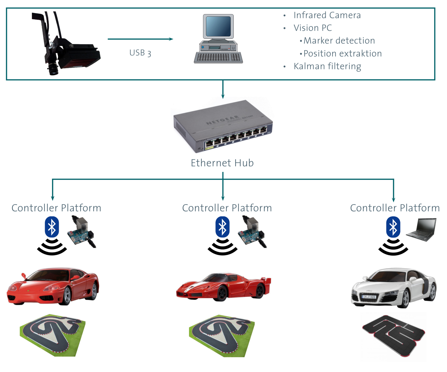
Control Loop Overview
- 1. The vision system captures the cars on the track, and it estimates the position and velocities of all cars.
- 2. The information is distributed over an Ethernet network to all control platforms.
- 3. The controller calculates the control inputs for the cars.
- 4. The control inputs are sent via Bluetooth to the embedded car which then drives around the track.
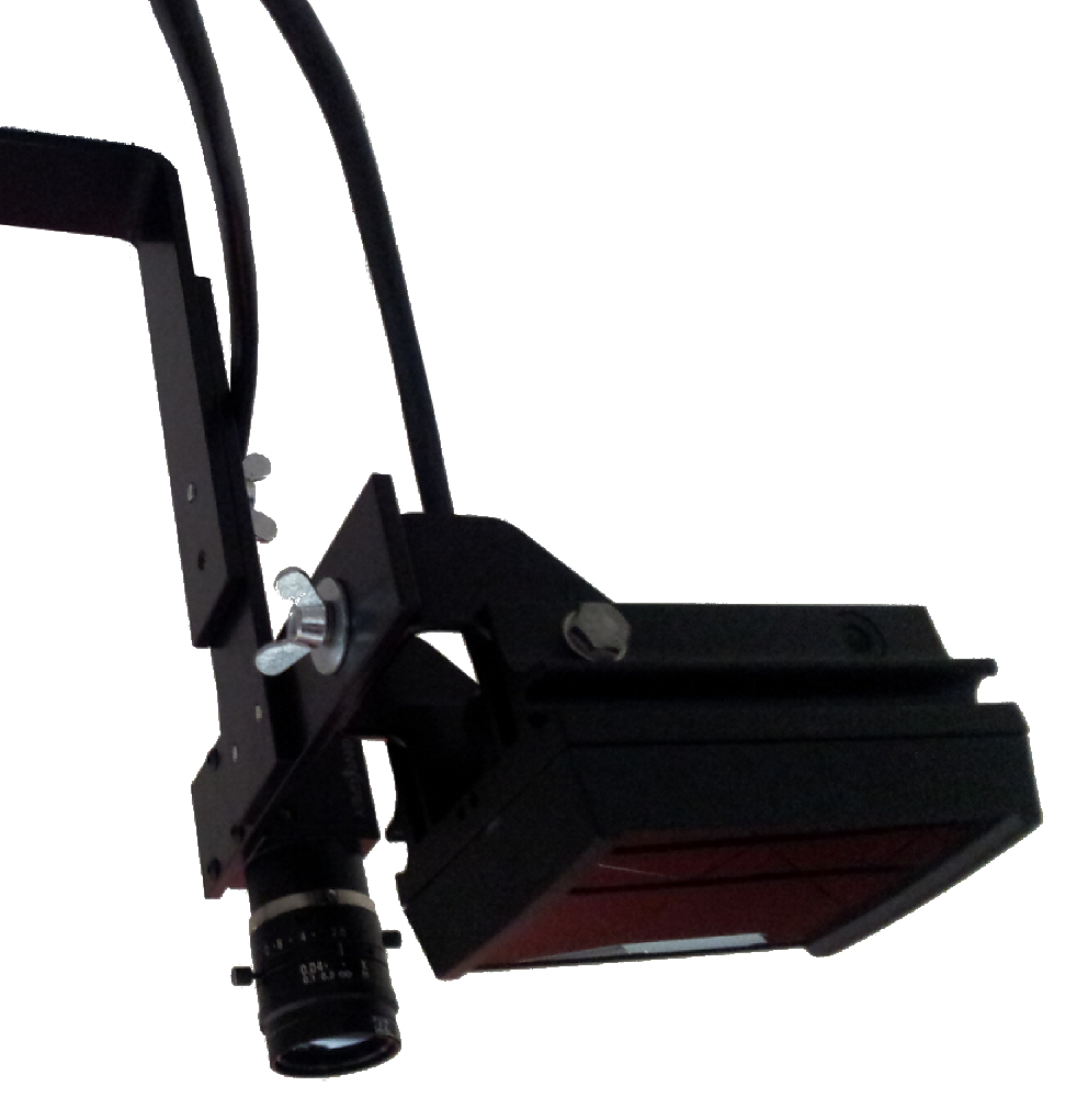
Camera System:
- external page PointGrey Flea USB 3 camera, with up to 150 fps at a resolution of 1280 x 1024 pixels
- Professional infrared spot for surveillance
- Fixed wide angle lens and infrared filter
Working principle:
Beside the camera an infrared LED spot is mounted, the light from the spot is then reflected by retro reflective markers on the cars. In front of the camera an infrared light filter is mounted such that only the reflected infrared light reaches the image sensor. Thus only the markers are bright spots in the image and they can be easily found using a simple threshold technique.
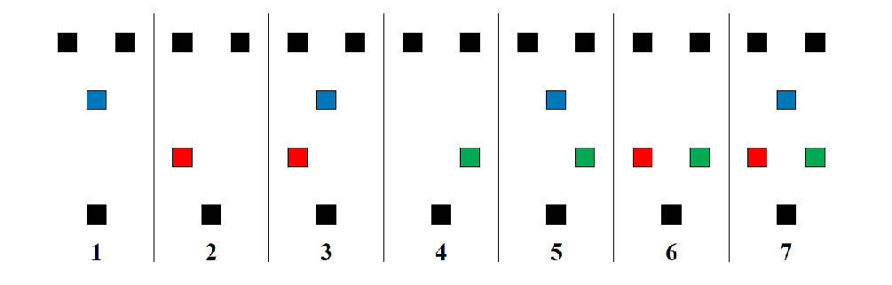
By using different unique marker patterns, the position and orientation of the different cars can be calculated using the blobs in the thresholded picture.
Vision Software:
- Thresholding and marker detection
- Car identification using patterns
- Extended Kalman filter for position and velocity estimation
Result:
- Resolution of 3.36 mm on a 4x4 m track
Control Platforms
The current set up allows for many different control platforms.
The key point of the set up is the Vision System, which distributes the data over a Ethernet network to all attached platforms. The control platform then has to send the control inputs to the Embedded Car using Bluetooth. Thus the control platform needs a Ethernet port and a USB port or another serial port to communicate over Bluetooth. The operation system of the control platform needs to be real time compatible, currently two systems are used for this purpose
- C++ control frame work, which runs on any Debian Linux operating system
- Matlab Real-Time Windows Target
The C++ control frame work is very flexible and can be used on powerful desktop PCs or on low cost embedded platforms, such as:
- Odriod U2
- Raspberry Pi
- Any Laptop or Desktop PC running Debian/Ubuntu
Embedded Car
The original electronic only has very limited capabilities. The main problem is the proprietary communication, as well as the internal control loops which are unknown and introduce a lot of uncertainties. Furthermore, original electronics do not have any sensing capabilities, which is emphasized for a good state estimation. Thus, the original electronics is replaced with a custom board which has exactly the same dimensions as the original board, but eliminates the problem of the original electronics.
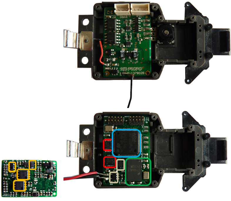
Features:
- ARM Cortex M4 Microcontroller
- Bluetooth communication
- H-Bridges: Steering control, Drive train motor
- Sensors: Gyroscope, Accelerometer, Motor current, Battery voltage
The embedded board has a powerful microcontroller, which allows on board low level control, a Bluetooth chip for communication in both directions at a known sampling time and all necessary sensors for advanced state estimation. Additionally, further sensors, as for example a wheel speed sensor, can be added using external connectors.
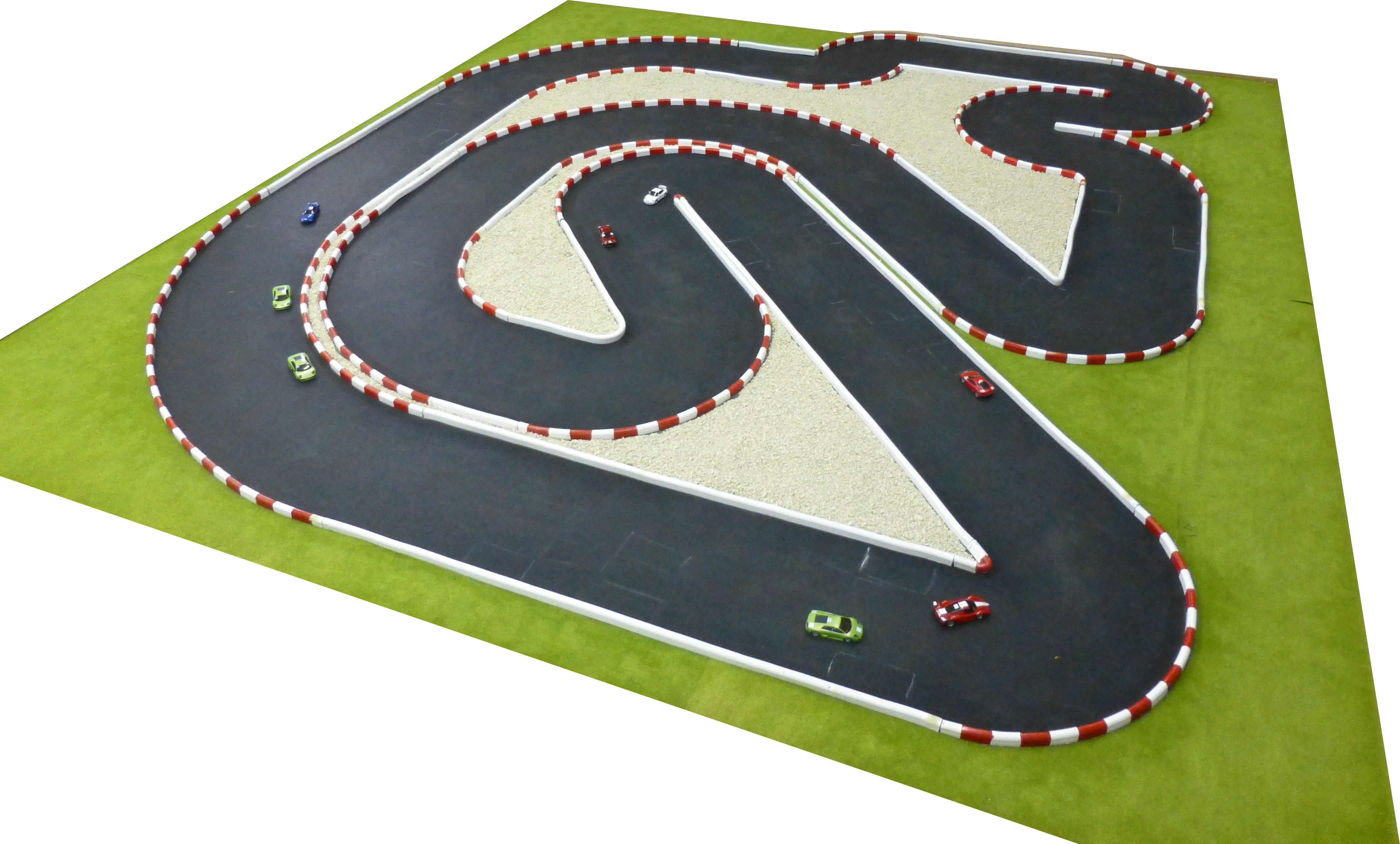
There is one main fix track mounted in the ETL D12.
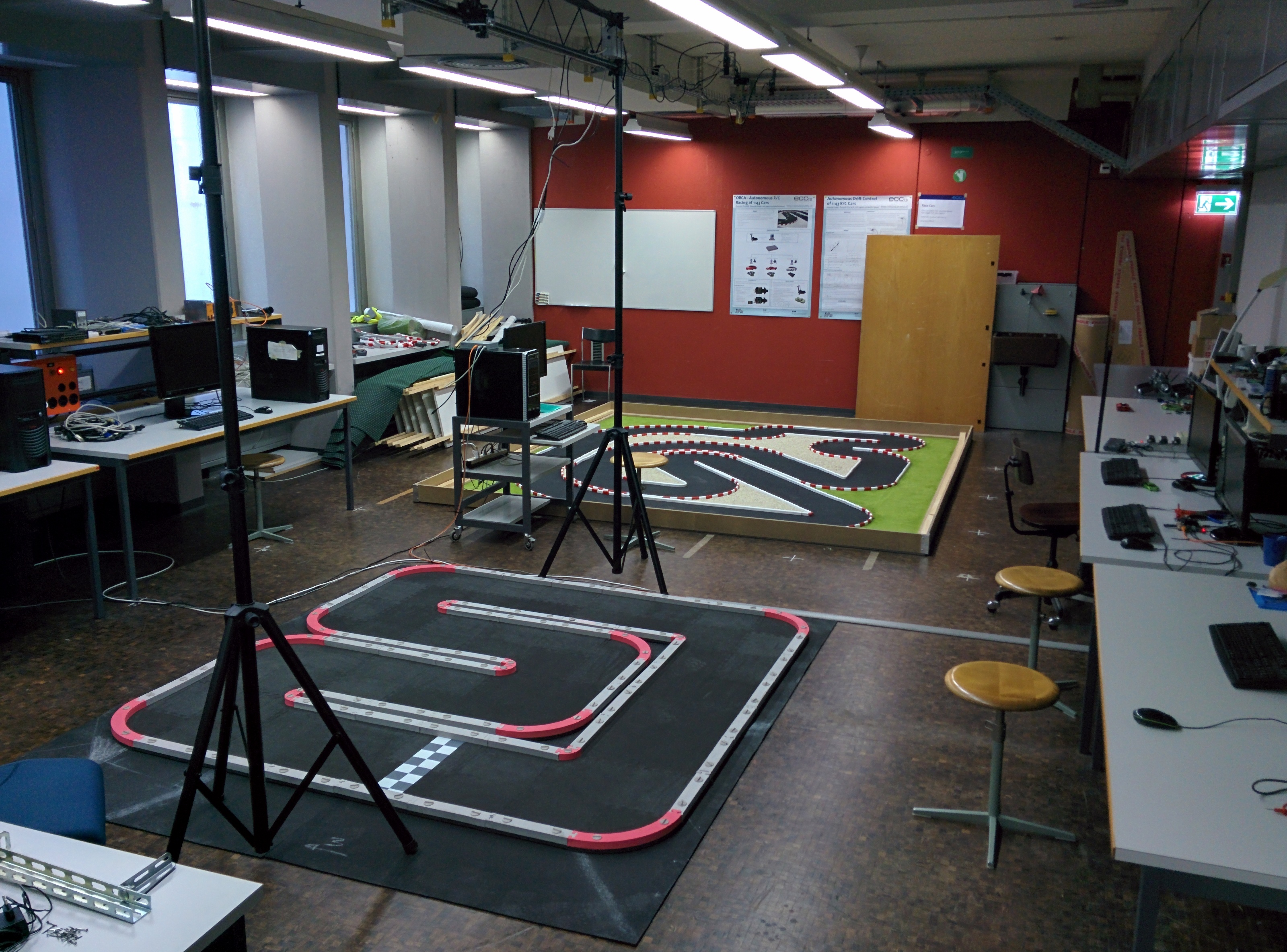
Beside the fix track there is a mobile RCP-Track, for external demonstrations, and a 2 x 2 m area with the same track material as the fix track, for system identification. Everything is placed in the room ETL D12.