Autonomous solar electric vehicle
This research project is currently not active and this page is not regularly updated. It is provided here for archival purposes.

The aim of the "Autonomous Solar Electric Vehicle" project is the investigation and realization of a reduced scale autonomous solar electrical vehicle. The project covers many different engineering disciplines including automatic control, power electronics, electric drives, mechatronics, telecommunication and embedded computation. We provide a platform that:
- allows graduate students to learn and gain experience in the fields of control, power electronics and embedded computation
- allows researchers to investigate, implement and validate advanced control concepts related to electric vehicles.
The project is largely carried out through a series of student projects that deal with different aspects of the overall project. The main parts of the project are:
Research directions and objectives
The project is developed along different paths to achieve the following objectives:
- Power electronics and control ⇒ energy efficiency
- Vehicle motion control ⇒ stability, trajectory control
- Autonomous vehicle control ⇒ autonomous driving, obstacle avoidance
Although a reduced scale vehicle is realized for testing, we are mostly interested in techniques that can be applied to real scale vehicles and thus can be transferred to the development of autonomously driving cars. A constraint that is imposed by the reduced scale of the vehicle is that the computational complexity of the control is a crucial aspect in the vehicle design that conditions the overall project orientation.
Hardware design and implementation
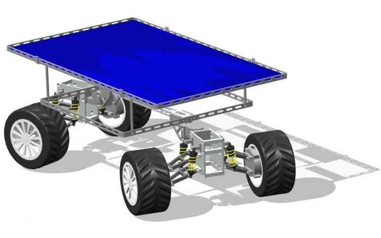
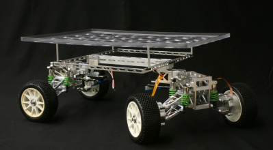
For implementation and testing purposes a reduced-scale vehicle has been built. It consists of an aluminium frame holding the solar panel, lead batteries, super-capacitors, two independently driven front wheels and four printed circuit boards (PCBs) housing the power electronic curcuits and control software. An Inertial Measurement Unit (IMU), cheap camera and a line laser (for obstacle detection) provides the necessary sensory information.

In the first phase of the project, potential applications were identified. The size of the vehicle, the mechanical constraints and the power and energy requirements were determined. To allow simple machining and a light-weight construction, the vehicle frame was built from aluminium. The two front wheels are motioned by mechanically independent permanent magnet synchronous motors. The selected motors are extremely efficient due to a high power density and can be used to recover breaking energy (recuperation). Steering is acomplished by applying a differential torque using the two motors, the back axis is fixed.
The power is generated by a 40cm x 30cm solar panel, generating up to 20 Watts. Solar power is used whenever possible and excess energy is storaged in the storage units. The vehicle's main storage units are two 24V, 0.8Ah, lead acid batteries, they are used as the main power source if the solar radiation is not sufficient to power the vehicle. Control hard- and software is managing the energy flow from the panel to the storage- or load units. Additional energy storage is provided by an array of super capacitors, used for short term storage of high power peaks. It consists of ten 100F capacitors operated at 2.7V
Conceptually the solar panel can deliver energy to the motors or supply an autonomous battery management system to charge the battery whenever the vehicle is in stand-by. The super capacitor array can store energy which is generated or used within a short time period. Either the capacitor stores energy from one of the other sources to be delivered to the motors, requiring a prediction algorithm to estimate the future power demand, or the capacitor can serve as a peak absorber for recuperation energy generated by the motors.
To control the power sources and storage units power electronic circuits and control hard- and software is needed. Two prited circuit boards (PCBs) have been developed in previous projects to support the required tasks. The first PCB is a generic power electronic control board, it contains inverters controlled by a micro-processor system, AT90SAM256 - a 32-bit ARM7 processor for real-time applications. It includes AD converters for current and voltage measuremens and PWM outputs for actuation as well as timers. It provides a low-power high-performance power electronics control platform. The second PCB is a signal processing and interfacing platform. The objectives of the board are real-time data processing tasks like interfacing a camera for object tracking and implementing a communication gateway to interface different control platforms. The platform integrates a micro processor as well as a Xilinx FPGA for highly parallel data processing.
For autonomous path-planning and driving we need to be able to determine the vehicle position and identify obstacles in our path. To achieve this the autonomous solar electric vehicle is equipped with an IMU to get orientation, velocity and acceleration feedback, which can be used to estimate the position of the vehicle relative to some starting point. It is also equipped with sensors to enable obstacle detection. Low-range ultra-sonic sensors detect obstacles in the immediate vicinity to the vehicle and avoid crashing by initiating an emergency stop when needed. A line laser combined with a low-cost, low-power camera detectes obstacles in front of the vehicle via triangulation, allowing to accurately measure the distance to obstacles in the field-of-view. Furthermore the camera could be utilized to compute relative position estimates based on computer vision techniques such as "structure from motion", combined with the IMU this would allow to estimate the vehicle pose accurately and without drift.
Power electronics, energy management & control
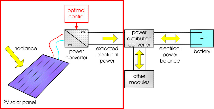
Energy management is another crucial part of an electrical vehicle. Energy is taken from an array of photovoltaic solar cells. Electrical energy that is not consumed by the vehicle is stored in a electrochemical battery. Power converters are used to interface the different vehicle modules (solar panel, battery, ultra-capacitors, electric drives, control and communications modules) that produce, store or consume electrical energy. We seek for the optimal power converter solution and control strategy to transmit the energy between the different vehicle modules in the most efficient way. The objective are to:
- maintain the photovoltaic solar panel at its maximum efficiency
- transmit energy between the vehicle modules in the most efficient way
- dynamically power control hardware depending on available energy and control objectives
Different converter structures can be used and they can be combined in different configurations, using different control strategies. This affects the vehicle cost, weight and efficiency and is an important topic investigated in this project.

The power drawn from solar panel needs to be controlled precisely to achieve good performance. For a given solar irradiance (light intensity) and panel temperature, the power that can be extracted from a photovoltaic solar panel depends on the (equivalent) resistance of its load. In this context, the role of the power converter is to provide a load of variable resistance and the role of the control is to track the resistance for which the power production is maximal. Among the different control techniques available, the most appropriate for vehicle applications are investigated and improved.
Different power modules (battery, ultra capacitor, solar panel, ...) need to be integrated and controlled such as to minimize the power losses and maximize lifetime of the components. We investigate algorithms for efficient power sharing, also including load forcasting and implement strategies to dynamically save energy by powering of control hardware and sensors that are not needed.
Control, estimation & identification of electric drives
The largest consumers of power are the two electic drives, thus the dynamic performance of the drives is of paramount importance to this project. The drive performance, and thus efficiency, of the drive hinges on three important areas: The control algorithm, the quality of state estimates used by the controller and the quality of the model used by the controller.
Permanent magnet motors are used as they feature high power density, efficiency and dynamic performance. However the dynamic performance and energy efficiency are also strongly influenced by the applied control strategy. We use a predictive control strategy to follow a torque reference given by the higher-level trajectory controller. Explicit model predictive controllers (MPC) are implemented in on the motion-control board.
The internal states of the motor are estimated using a back-electromotive force (back-EMF) observer and using motor orientation measurements from the hall effect sensor. More sophisticated estimators and encoderless/sensorless techniques for estimating the motor orientation with higher accuracy than possible with the hall sensors remain open topics. Furthermore reliability & security enhancements, such as automatic breaking in case of failure, need to be investigated further.
A simple model of the motor is used for control and estimation. Model parameters were taken directly from the datasheet of the motor. Robustness and performance of the feedback loop could be improved if more accurate model parameters were used and if time-varying motor parameters, such as the stator resistance - which is temperature dependent - were identified continuously.
Based on a model of the vehicle dynamics we want to follow a pre-planned trajectory given by the higher-level path- and objective-planning entity. A robust H-infinity waypoint tracking controller is implemented that is based on a simple dynamic model of the vehicle. However the current controller has no knowledge about the non-holonomic behavior or more complex dynamics such as wheel slip. This leads to steady-state errors. A more sophisticated control method based on a more accurate model could achieve better performance.
The vehicle pose is esimated using odometry and is thus highly suceptible to drift due to measurement errors and biases. To further improve the tracking performance the vehicle pose needs to be known with higher accuracy. Sensors to adjust for biases introduced by wheel slip and to avoid the accumulation of errors are in place. The IMU is used to more accurately track the performance but still does not provide an absolute reference. To avoid drifting estimates and have bounded position errors the camera interface could be used in later projects and combined with computer vision algorithms to track the distance to goal points.
The vehicle should be able to plan trajectories that are optimal with respect to some cost function, e.g. to minimize expended energy, minimize arrival time or similar. Furthermore the trajectories should be safe, in the sense that they obey operational and safety constraints for the vehicle, as well as avoid obstacles. Preliminary studies have investigated the generation of power-optimal trajectories, the efficient planning of trajectories and how obstacles can be avoided using the available sensing equipment. The vehicle uses ultra-sonic sensors for emergency stops and a laser range sensor that has been developed to detect obstacles. An efficient heuristic algorithm for path-planning and obstacle avoidance has been developed, focusing on low computational complexity but still ensuring smooth trajectories that are feasible for the vehicle. However the currently implemented obstacle detection and path-planning algorithm remains to be fully integrated, as it requires image processing that is not feasible on the microcontrollers and needs to be implemented on an FPGA.